Wednesday, 5 May 2021

Upgrade BSNL FTTH plans online without visiting BSNL office

 Due to the corona pandemic many IT people have moved out of big cities and started working from their home in villages / small cities. Having a good internet connection is a crucial thing for many people who are working from home. Thanks to BSNL for providing FTTH connection to many villages across the India. I am personally satisfied with the speed and service provided by BSNL in my area. 

Like most of the people I hate visiting government offices 😃 Visiting the office physically when the things can be done online is not convenient to anyone. Recently I tried to upgrade my BSNL plan. It was not very straight forward ! So I am trying to explain this in a step by step manner. 

Step1 : Sign-Up BSNL Self Care portal

Many things like bill payments, complaint register and upgrade can be done through BSNL Selfcare portal. To begin with you need to sign-up to the portal using the Email-ID and mobile number 


The email ID will be your username to login to the portal. You need to provide the same email ID as the one in which you are receiving your monthly bill. The mobile number should be the registered mobile number. 

If you don't remember these IDs, dont worry, I have a hacky solution for you 😀

Download My BSNL app


Launch this app and press "Skip Login". Inside the app you can choose "Update Register Mobile Number" tab. This will take the registered landline number and show you the email ID and the mobile number 😀. This looks like a security breach, hope they will fix it soon. 

You will receive an OTP to verify the mobile number. Also you need to verify the email ID by clicking the link sent to it. 

Step 2 : Log into selfcare and add service account

Once you have logged into your portal you need to add the service account corresponds to your landline. 


This can be found under "Manage Account".


Here comes the tricky part. You need to choose "Wireless", "Normal" for FTTH. 


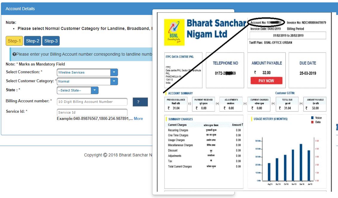
For the billing number you need to check the bill copy that you got as shown in the figure. 

For the Service ID you need to give your landline number with hyphen, example :
080-123456
Dont forget to specify the hyphen (-) after area code !!

This is a bad validation from BSNL side, but cannot help. 

Some times you will get error like "No such Customer is registered with us". In that case try providing the service ID without '0'. 
Try out the things suggested in the below site :

Step 3 : Upgrade your data plan

Once you have added your account, you can click on your billing account and opt for upgrading the plan.


Follow the plans and choose the right one for you. You will have to wait for around 5 days to get the plan applied. 

Hope this will be helpful for you. Please feel free to add more tricks in the comment. 

Tuesday, 1 November 2016

Speaker and Language recognition using GMM with matlab codes

Speaker recognition can be done effectively using MFCC features and fitting a Gaussian Mixture Model. In our project we had the data from 22 different speakers. Each speaker were having 8 voice samples for the training. A GMM model was fit for each speaker. When a new test voice comes the likelyhood of the voice is computed for all the speaker models and the one with the highest likelyhood will identified as the speaker.

A detail description and codes are present in the following link

Speaker recognition matlab code

Wednesday, 3 July 2013

Simple Speech Recognition System Using LPC

Theory:

Linear Predictive Coding:

Linear prediction means  predicting the next sample using the previous samples.Theory is given below.


w(0),w(1)...w(p-1) are called the LPC coefficients.


As we can see the LPC coefficients captures almost all formant frequencies.So we can effectively represent the voice samples through a lesser number of coefficients.
These coefficients are used train the neural network to classify the voice signals.

Neural Network:


It is a net like structure which takes the features x1,x2.....xn to classify it as one of the outputs.Theory is given below.


Implementation:

1.Record the voice samples for 1 second with the sampling rate of 8000.So we will get 8000 samples.
2.Noise removal:

3.After removing the noise by keeping the threshold
number of samples will be reduced greatly.
It is passed through high pass filter to boost the high frequency components,since the high frequency components are more susceptible for noise.
4.Frame blocking:
Array of voice samples are divided into many number of overlapping blocks.This is done because over the small length of the block we can assume the process as WSS process.
We have taken the block length as 240 samples and the overlapping as 80 samples.So the first block will be from 0 to 239 and the second block will start from the index 160 i.e (240-80).
5.Hamming window:
Each block is multiplied by the hamming window.This is done because if we consider the block directly for the analysis there will be sudden discontinuity at the ends.So to remove the sudden discontinuity the ends are tapered using the hamming window.

So the ends will be attenuated in the process.That is why we consider the overlapping windows in order to accommodate all the information correctly.
 6.Auto correlation Matrix Formation:
The matrix is formed as explained in the theory.


 LPC coefficients are obtained for the each block.

These coefficients obtained are used to train the neural network.To get accurate result many samples are required to train it.
In our examples we tell the numbers from 0 to 9 and the system should recognize it and display the number.
We trained 15 samples of each 0 to 9 in a constant acoustic and   could achieve an accuracy of 90 % for a speaker.


Matlab files:

MATLAB LPC.rar


Steps to be followed after downloading matlab files:

1.Open normalizedlpc.m file and run it.
2.It will ask you to record your voice.Record a number after pressing enter.
3.Give the corresponding number when it ask to enter the number.
4.When you tell 'zero',instead of giving the number as 0,give it as 10.(because the program uses the entered number as indices and the matlab does not contain 0th index)
5.After repeating from 0 to 9,again start from 0,it will ask u to record 30 samples.
6.Each number should repeat for thrice in 30 samples,their order does not matter.
7.The LPC coefficients will be stored in variable X and the numbers will be in Y.These two variables will be stored in lpcdata,mat file.
8.Load the normlpcdatabase.mat file, copy X and Y to K and L respectively.Save these variable back to the normlpcdatabase.mat file.
9.Again run  normalizedlpc.m file to collect next 30 training samples,accumulate X and Y to K and L to creat  
large database.
10.After collecting 150 to 180 training samples run lpcnuralnet.m file.It will train the neural network using back propagation algorithm.
11.Finally run the voicepredict.m file to check the prediction.
12.By increasing the training samples,and doing it in different acoustics the prediction accuracy can be increased.

This program can be easily altered to recognize other words also.
All kind of suggestions are welcome.


Monday, 27 August 2012

Simple Arduino Capacitance Meter


Simple Arduino Capacitance Meter

Description:
This is a device to measure the capacitance.It is constructed using the arduino bord.It just consist of a fixed resistor and a capacitor whose value is to be measured.Its practical measuring range is limited to 200nF to 300uF due to various reasons.
Principle of working:


Its principle is very simple.The capacitor shown in the figure is is fully charged and then allow to discharge through the resistor of fixed resistance.The discharging equation is given by .So  initial voltage of the capacitor V0 become constant.If we fix the V(t), it will also become a constant.Anyway resistor is fixed.So if we write the equation for capacitance from this equation, it clearly shows that the capacitance is linearly varying w.r.to time.It means if 1uF capacitor takes 1ms to discharge from 5v to 1v,then 2uF should take 2ms to discharge fro 5 to 1v.So we are measuring the time taken by a known capacitor,and using linear relationship we can calculate the unknown capacitor value.
Construction:
The pin 1 is connected to digital pin 7(d7),of the arduino.And the pin 2 is connected to the analog pin A0 (a0)in arduino.First we need to charge the capacitor fully.So configure d7 as output and give a high voltage,configure a0 as output and give a high voltage.Give a delay time to charge the capacitor fully.After the delay make d7 low and configure a0 as analog input.The capacitor will immediately start discharging and the reading will be measuring in a0.Start the inbuilt timer to calculate the running time.After the capacitor voltage decrease to certain value say 2v, stop the timer and calculate the time.At first time we should be knowing the capacitor value.Using this data the
Cunknown=(Time taken for unknown X known capacitance) /(Time taken for the known capacitor);
Use the lcd to display the output.For very smaller value of capacitors the dischage time will be in nanoseconds.So we are ending up with more error.By choosing the resistance of higher value the range can be increased.
arduino code:

#include <LiquidCrystal.h>
LiquidCrystal lcd(12, 11, 5, 4, 3, 2);
void setup() {

TCCR1B=0x00; //stop timer
TCCR1A = 0x00; //normal timer mode
TCNT1=0x00;//initial value of the timer
pinMode(7,OUTPUT);
digitalWrite(7,HIGH);
pinMode(0,OUTPUT);
analogWrite(0,255);
delay(3000);//charging the capacitor
digitalWrite(7,LOW);//start discharging
pinMode(0,INPUT);
TCCR1B = 0xC3;//start timer
int x;
while(1)//wait in the loop until cap discharge to 2.5 volts.
{
  x=analogRead(0);
 if(x<=410)break;
}
TCCR1B=0x00; //stop timer
long k;
k=TCNT1;//final value in the timer
double c;
c=(10000*k/2348);// for 10000 nF it took k=2348.
lcd.begin(16, 2);//start timer (clock prescaler /64)
if (c<1000) {lcd.print(c); lcd.print(" nanoF");}
  else {lcd.print(c/1000.0); lcd.print(" microF");}

}
void loop()
{

}


Implementation In LabView


If u have any suggestion in improving this please feel free to comment.
Have fun....
Team members:
Dheeraj kumar C.
Kumar bharath
Darshan ramakant.


Sunday, 26 August 2012

Cellphone Operated Robot


                                       Cellphone Operated Robot

Description:
It is basically a robotic car which can be controlled using mobile phone.The key component in this robot is DTMF decoder ic.It takes the dualtone frequency as input and produces output in binary form.In cellphones when we press any key we will listen different tones.That tone is a linear combinations of two sinosoids of different frequencies.Here is the table.


The dtmf decoder takes these frequencies and gives binary outputs.We will give the input tone to dtmf decoder using audio jack from phone 1. We call this number using phone 2 and press buttons,the tons will go to decoder through adio jack and the ic will produce different binary outputs for different key pressed.These binary output can be used to control the robot using microcontroller.
Circuit:


The tip is connected to the tip of the adio jack.ring is connected to the bottom ring of the adio jack.


The two other end points in right side of dtmf circuits  are connected to the 9v battery.The output will be taken from Q1 to Q4.The output buffers are not necessary.

Connect the other end of the jack to audio pin of the phone.Keep the phone in automatic answer mode.Call this number from other phone.As u press the keys the output starts coming.Put LED's to test.When u press 1 in mobile Q1=9volts,Q2=Q3=Q4=0.Similarly when u press 2, Q2 becomes high and so on.These outputs are taken and given to 8051 micro-controller.The output of the microcontroller is given to the H-bridge ic to control the motor rotation of the robot.
So we can control this robot almost anywhere in the world,if u can establish call from a mobile to the cellphone in the robot! The area of operation is same as the area of the service provider.
Not only this robot we can trigger any circuit by using this amazing ic.
You can see the final product video at this link

Team members:
Dheeraj kumar c
Kumar bharat
Darshan ramakant


Have fun..

Saturday, 18 August 2012

My theme

Hello guys.This is my small attempt to do something in electronics.First of all let me tell about myself.I
am  from a small village in the Karnataka.Now i am doing engineering in PESIT Bangalore in electronics.                                                                                                                                                  
                What i have seen so far is most of the technical people are contributing to domain which is mainly  related to the entertaining field.For example many apps now available are to entertain the people and helping the people to pass the time.But we are forgetting the primary part... agriculture ,farmers who are feeding us.There are lot of problems in that field.Recently what i have seen is there is lot of shortage of manpower in that field.every one wants to get a job in an air conditioned office.No one is preferring to work in the field.As i am also in that traditional path i have no moral rights to force anyone to choose agriculture.But i want to help them through the technology.We can do something to help them.
        I will be uploading the projects we did.These projects may not entirely our own.We might have copied the circuits from the other sites.But the whole idea is to build something  from which we know.
You guys are always welcome to give suggestions...